الاقسام
منتجات جديدة
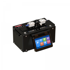
LDC-100 ساطور ألياف بصرية بقطر كبير * قابل للتطبيق على ألياف قطرها 80μm ~ 600μm *مضخة فراغية V-groove ملائمة لوضع الألياف *شفرة قابلة للتبديل ، عمرها أكثر من 20000 مرة *تخزين البيانات 4000 مجموعة * قائمة واجهة المستخدم الرسومية سهلة الاستخدام ، وسهلة التشغيل أكثر من
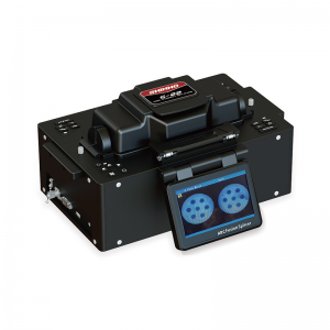
جهاز فصل الألياف متعدد النواة S-22 الجهاز الأول بالكامل من نوع M فائق النوى F iber F usion S في الصين أكثر من
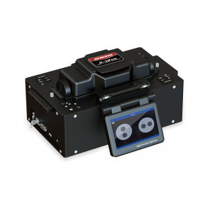
الاستقطاب الحفاظ على الألياف (بعد الظهر) فالانصهار S-12 * النواة الأساسية المحاذاة ، منخفضة الربط الخسارة * Endview الشخصي والمراقبة المحاذاة * قوس المعايرة التلقائية و الربط * مساء الألياف 45 و 90 درجة التوافق أكثر من
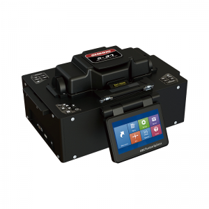
S-37 LDF Speialty Fiber Fusion Splicer SHINHO S-37 هو أحدث طراز قمنا بتطويره ، يمكنه لصق قطر الكسوة الليفية من 125 إلى 400 ميكرومتر مع فقدان لصق منخفض. جهزنا الماكينة بثلاثة حوامل ألياف مختلفة وزوجين من الأقطاب الكهربائية الاحتياطية. أكثر من
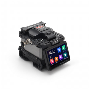
الأساسية إلى الأساسية محاذاة الألياف الانصهار جهاز الربط X900 ستة محاور الانصهار جهاز الربط ، الأساسية الحقيقية لتكنولوجيا المحاذاة الأساسية. 6S الربط ، 16S التدفئة ، وتحديد أنواع الألياف تلقائيا. تستخدم ل wan / رجل / مشاريع الاتصالات السلكية واللاسلكية. أكثر من
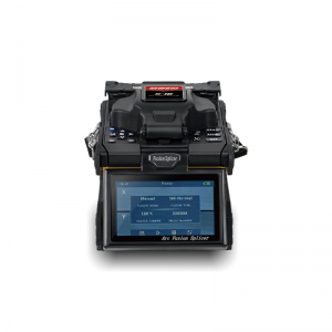
قوية متعددة الوظائف قوس الانصهار جهاز الربط s16 تصميم صناعي قوي ، ومكافحة صدمة ، مقاوم للأتربة ومقاوم للماء. حامل متعدد الوظائف للألياف العارية ، حبال التصحيح ، كابل إسقاط إلخ. الربط السريع والتسخين ، معايرة القوس التلقائية. أكثر من
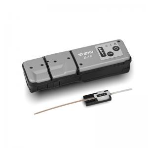
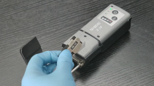
SHINHO X-18 قشارة ألياف حرارية للشريط Shinho X-18 Thermal Stripper عبارة عن متجرد حراري محمول باليد تم تطويره حديثًا ، مصمم خصيصًا للفصل الحراري غير المدمر لغطاء كابل الشريط حتى 12 ليفًا. أداة جيدة وموثوقة لأعمال الربط بالألياف الشريطية. أكثر من
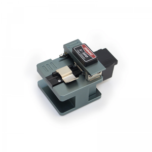
عالية الدقة الألياف البصرية كليفر X-50D حجم صغير وخفيف الوزن ، سهل التشغيل. دقة عالية وأداء مستقر. أكثر من 48000 عمر للشفرة ، f طول مشقوق iber 5 ~ 20mm. مواد ذات جودة عالية أكثر من
Ribbon Fiber Splicing Best Practices: How to Achieve Fast, Reliable, and Low-Loss Fusion Results
With the rapid development of 5G, data centers, and FTTH networks, ribbon fiber has become increasingly popular in backbone and metropolitan area networks due to its high density and improved construction efficiency. Compared with traditional single-fiber splicing, ribbon fiber allows multiple fibers (typically 4, 8, 12, or more) to be spliced simultaneously, greatly increasing productivity. However, it also requires higher precision and stricter operational control.
Ribbon fiber arranges multiple optical fibers side by side in a flat ribbon structure, usually with a pitch of 200 μm or 250 μm. Splicing is performed with a dedicated ribbon fusion splicer that uses V-grooves to hold and align multiple fibers for simultaneous fusion.
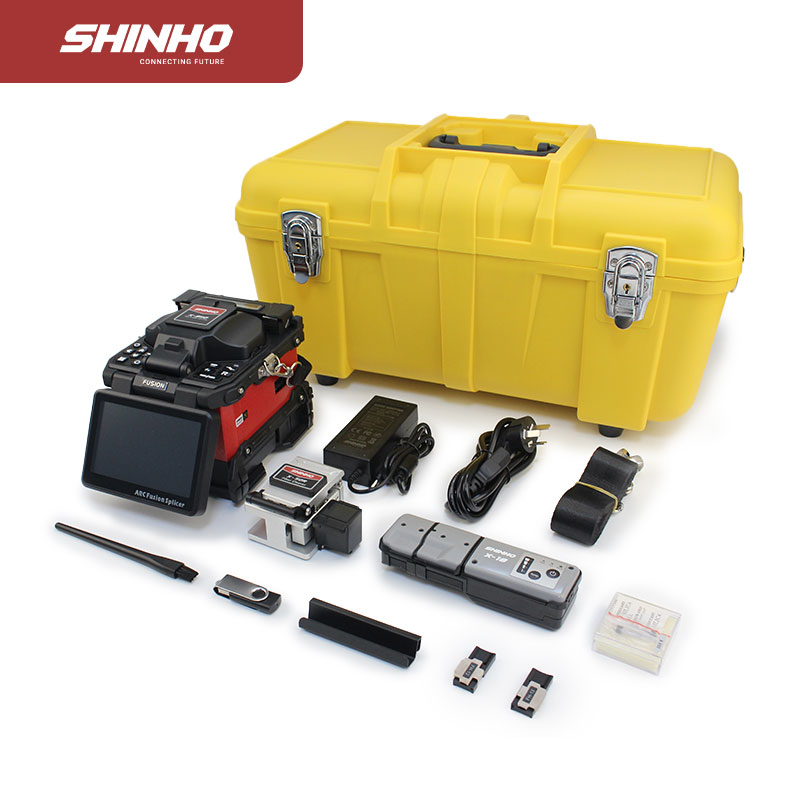
A representative example is the Shinho X950 fusion splicer, which supports splicing of 2–16 fibers and is supplied with a thermal stripper, cleaver, and other preparation tools. Its low splice loss makes it a dependable option for high-density optical network construction.
The main advantages of ribbon fiber splicing include significantly faster splicing through simultaneous multi-fiber processing, low average splice loss (typically below 0.1 dB per fiber), and suitability for high-density cable deployment. At the same time, inadequate preparation or incorrect operation can result in inconsistent loss among fibers, end-face contamination, or fiber breakage.
Preparation is the most critical stage because it directly affects the splice success rate.
Choose a clean, wind-free, dust-free environment with relative humidity below 70%, such as an indoor workspace or dedicated splicing tent. Dust and airflow can easily contaminate fiber end-faces and lead to splicing failures. Keep the workstation organized and have alcohol, lint-free wipes, and cleaning brushes ready before starting.
Prepare a ribbon fusion splicer with the appropriate ribbon holders or clamps, a thermal stripper to minimize mechanical damage during coating removal, a ribbon-specific precision cleaver, properly sized heat-shrink sleeves, high-purity isopropyl alcohol (99% or higher), fiber cleaning solution, and testing instruments such as an optical power meter or OTDR.
Expose roughly one meter of ribbon fiber from the cable by removing loose tubes and filling compounds. Use the thermal stripper to remove the coating uniformly, typically over a length of 30–40 mm. Clean the fibers thoroughly with alcohol until all coating residue, dust, and oil are removed. Because the fibers are connected in a ribbon structure, contamination on a single fiber can affect the entire ribbon. Finally, use a fiber arranging tool to ensure consistent spacing between fibers and to eliminate twisting or crossing.
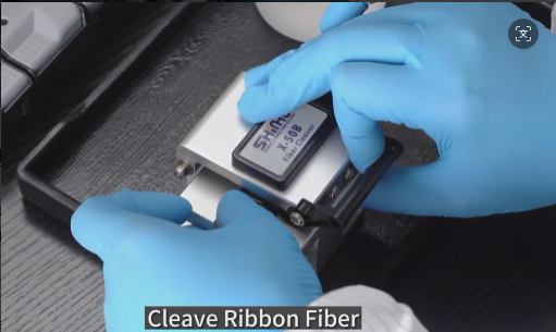
The fiber end-face must be flat, perpendicular, and free from cracks, burrs, or lip defects. A ribbon-specific cleaver should be used to cleave all fibers simultaneously, producing consistent bare fiber lengths of approximately 10–15 mm. After cleaving, place the fibers into the splicer immediately to avoid secondary contamination.
Select the correct V-groove according to the ribbon pitch (200 μm or 250 μm). Insert the ribbon so that it lies flat and is not reversed. Modern fusion splicers, including models such as the Shinho X950, generally provide automatic alignment, but operators should still verify alignment visually through the microscope. Close the clamps gently to avoid crushing the fibers.
Adjust parameters such as pre-arc current, splice current, and feed amount according to the fiber type (for example, G.652 or G.657) and the ambient temperature. Many advanced splicers include intelligent optimization features, but following the manufacturer's preset recommendations is advisable during initial operation. During fusion, observe the splice image to confirm that the splice point appears round, symmetrical, and free from bubbles or deformation.
Immediately position the heat-shrink sleeve over the splice and place it in the heater. Some splicers provide dual heaters to improve efficiency. Allow the sleeve to cool naturally after heating and verify that it has shrunk evenly, contains no bubbles, and provides secure mechanical protection.
Follow the standard fiber color code sequence carefully to avoid misconnection. Apply clear labels or color identification after splicing to simplify future maintenance and troubleshooting.
High splice loss is often caused by contaminated end-faces, poor cleaving, alignment errors, or incorrect splice parameters. The recommended corrective action is to clean, recleave, and re-splice the fibers. Fiber breakage commonly results from stripping damage, excessively small bending radii, or excessive clamp pressure. Inconsistent loss across multiple fibers is usually associated with pitch mismatch or uneven fiber arrangement; pitch-conversion holders can help address this issue. Equipment alarms may indicate contamination in the V-grooves, on the electrodes, or on the lenses, so regular cleaning and monitoring of blade and electrode life are essential. After each ribbon splice, perform bidirectional OTDR testing and re-splice any fiber whose loss exceeds 0.3 dB.
Daily maintenance should include cleaning the V-grooves, electrodes, and observation lenses, as well as replacing consumable parts at the recommended intervals.
Successful ribbon fiber splicing depends on four fundamentals: cleaning, cleaving, alignment, and protection. By following standardized procedures and maintaining proper equipment, technicians can achieve efficient, low-loss splicing that improves network performance and reduces long-term maintenance costs. In practical projects, targeted practice with the specific fusion splicer model and fiber type being used, along with careful reference to the manufacturer's technical documentation, will help ensure consistent, high-quality results.

مرحباً بك في تسجيل النشرة الإخبارية إذا كان لديك أي اهتمام بمنتجاتنا ، سنبقيك على علم بأخبارنا ، معلومات المنتجات والعروض الترويجية في حال وجودها.
© حقوق النشر: SHINHO OPTICS LIMITED كل الحقوق محفوظة.


 العربية
 English
 français
 русский
 italiano
 español
 português
 ไทย
ไทย हिन्दी
 Indonesia
 中文
中文